In this blog series, we’re exploring design for manufacture from its conception to the production line. In Part 2, we discussed how collaborating with you helps us better define the design objectives. Later, we’ll see why clearly communicating the design with drawings and renderings is so important. We’ll also outline five phases of custom computer production. Next, we need to prioritize the design goals, balancing them between the limits. In this post, let’s see where those boundaries are, and how they might guide us to the best solution.
Balancing Design Goals Within the Lines
If all computers were the same, they would all look the same. Yet each is more than a simple box with fans and card slots and mounting posts. Their unique challenges define their design, and every detail takes its own shape around them. Besides the imposed constraints of rack dimensions and desired features, there are intrinsic limits of material and process that also drive the end results.
Thickness adds strength. But, when sheet metal is punched its thickness limits how closely those holes can be positioned to other edges and bends. Additional bends add rigidity. But each bend adds another step to fabrication and increases cost. We could reduce some cost by using pre-plated material. However, post-plating also protects the cut edges from corrosion. Finding the right balance between limits like these allows us to maximize the system’s potential. Prioritizing your design goals helps us determine where that balance point should be.
Limits Set by Some Desired Features
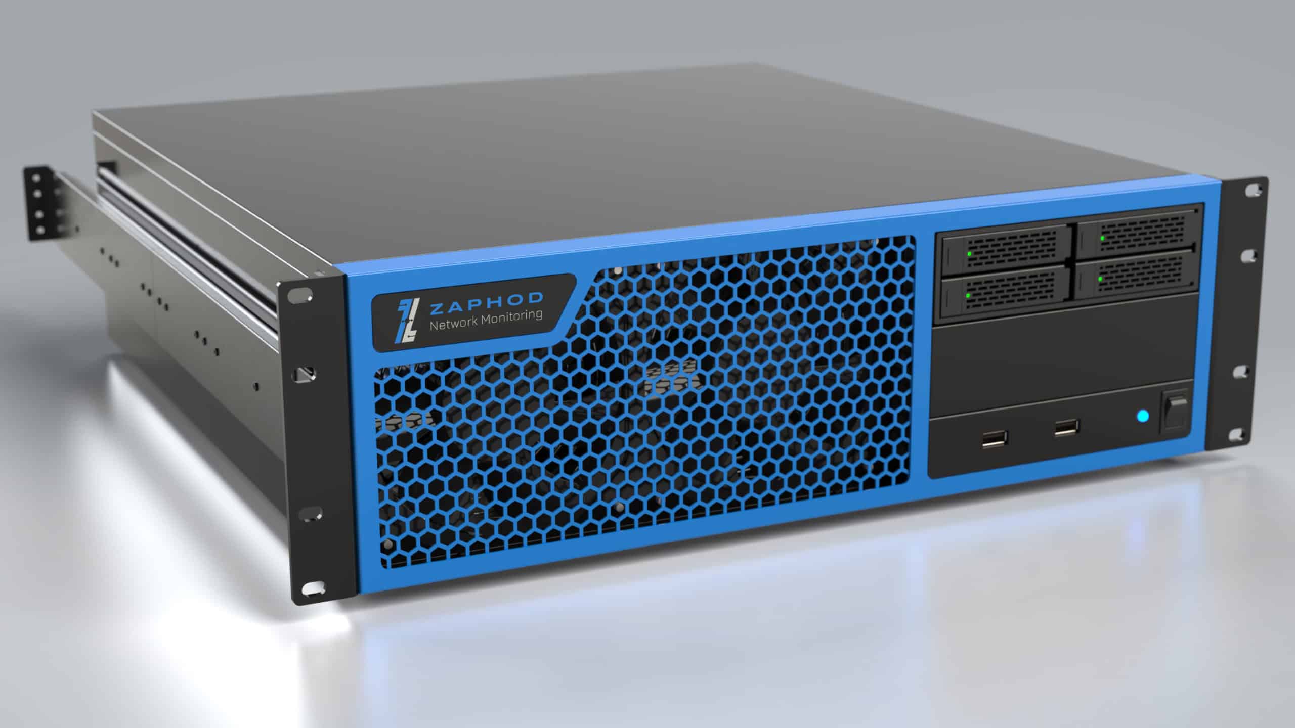
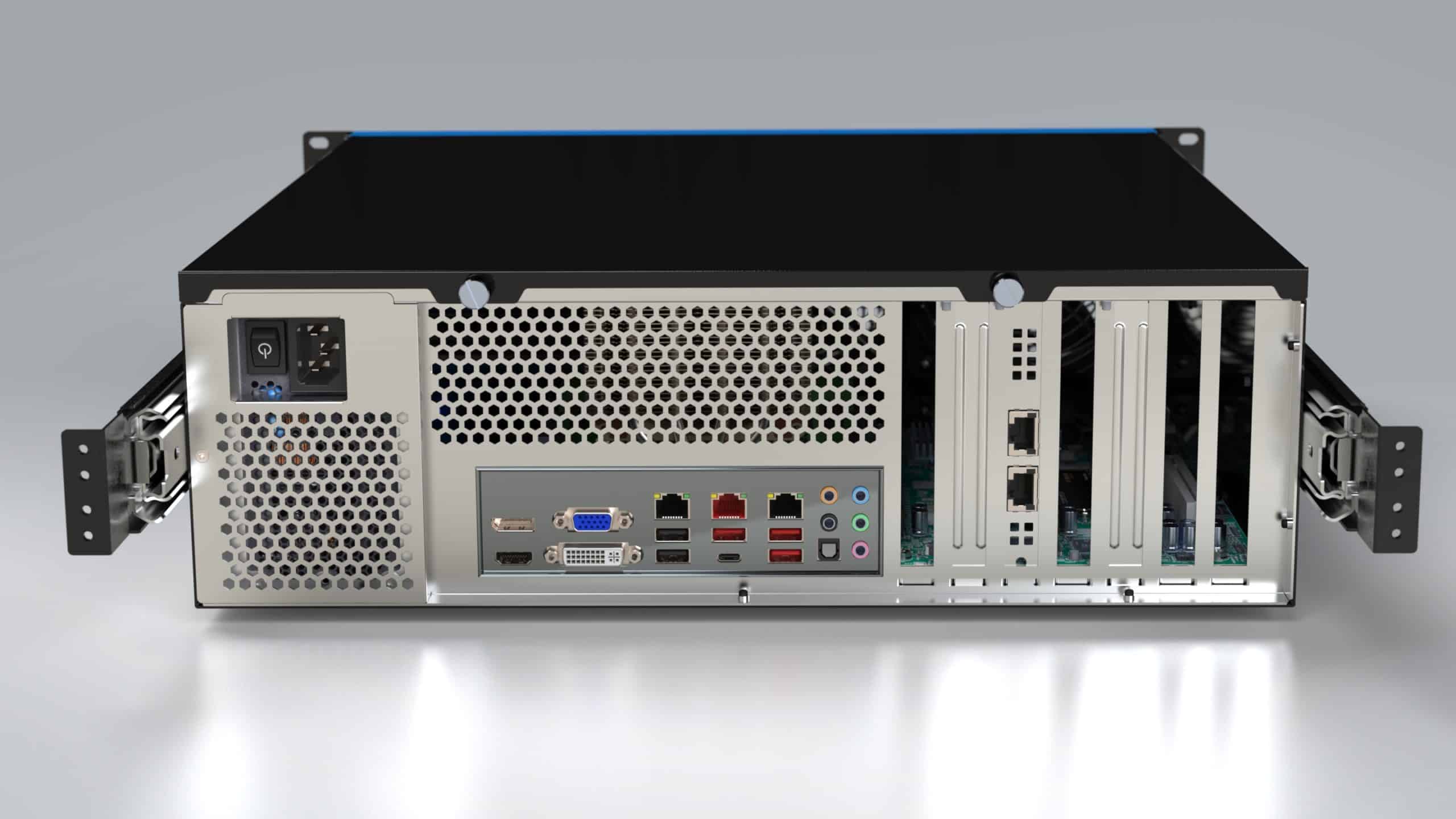
For example, there are only so many features that can physically fit on the front panel of a rackmount chassis. But we’ll ensure that the controls and indicators you need are accessible, that ventilation is sufficient, and that air is channeled to the components that need cooling.
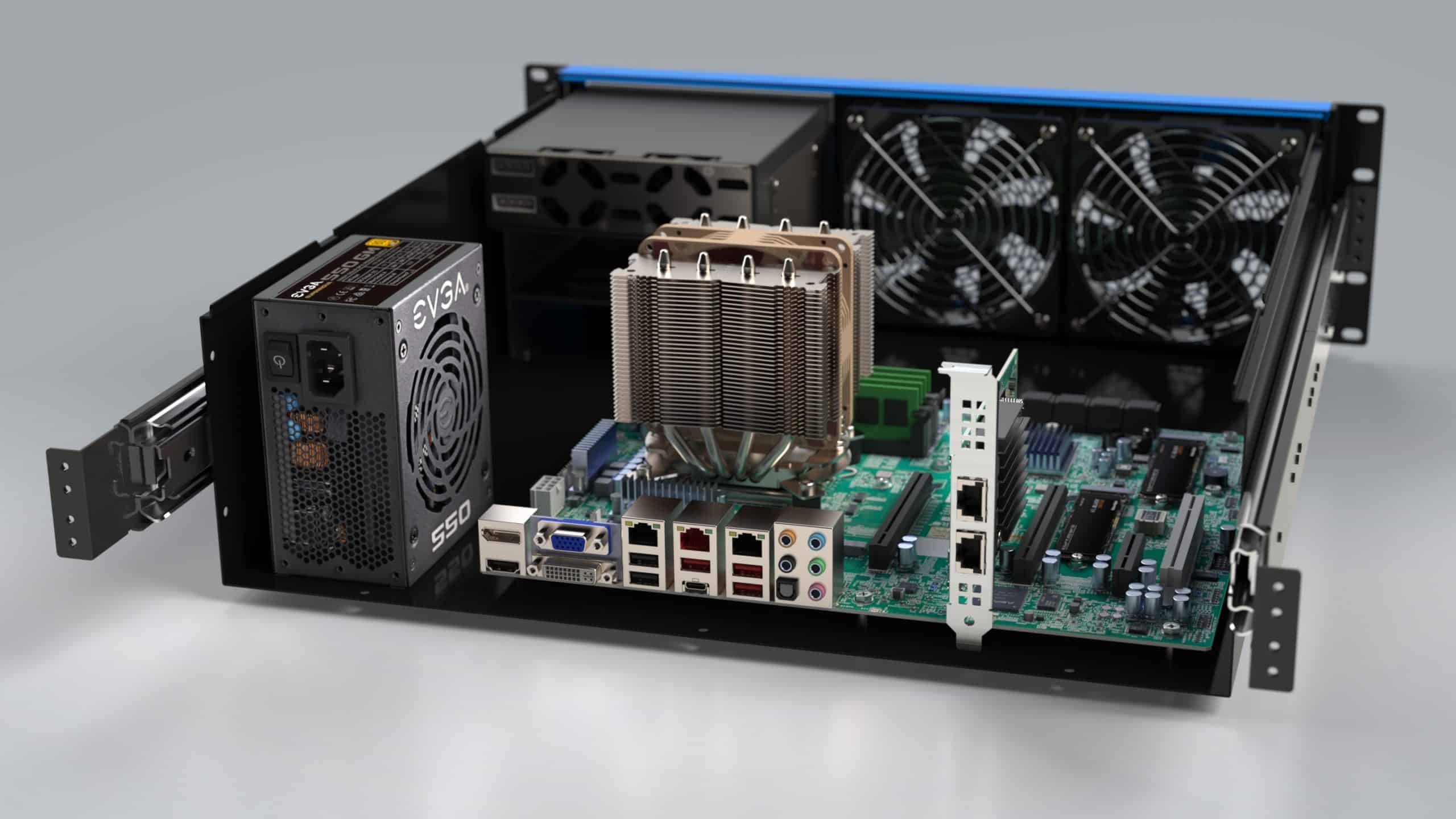
If filters are required, more space should be reserved in front of and behind them to reduce the impedance they introduce. For proper filtration, chassis fans should be near the front, behind the filters. Pressurizing the chassis this way with intake fans is critical when operating in a dirty environment. Exhaust fans would turn every other opening, intentional or not, into an air inlet. That would create unexpected paths for airborne dust or grease to bypass the filters and build up on heat sinks and sensitive components. In this case the priority of filtration sets limits for the fan location, component placement, and minimum chassis depth.
Similarly, if reducing noise were the higher priority, we would suggest using larger and slower fans. We would also minimize air impedance with as much ventilation area as the front and rear panels allow, and use larger heat sinks. This sets a limit for the minimum height to preferably 3U or taller, and reduces the available area on the front for controls or removable media.
How Can We Take it Further?
As we include more desired features the design grows in complexity. We will further reshape the design to simplify it, reduce the part count, and stay within your budget. Each of these challenges, when fully explored, lead us towards the final design. Continue reading Part 4, and we’ll see what more we can do to make your product stand out.